1.type of package material
At present, there are various types of package material in the market. For example, there are types of metal, non-metal, glossy, dull glossy, one layer, complex and co-extrusion package materials. Some of them are of high cost (such as aluminum and EVOH). On the premise of meeting testing requirement, the smaller the thickness, the lower the cost of package material is. Over-thickness will not only cause the waste of material but also reduce productivity effect. Obviously, thickness of the material is controlled and can only be measured by thickness tester.
2.Mechanical thickness tester
From the perspective of testing principle, the commonly used thickness testes are laser thickness tester, capacitive thickness tester, eddy current thickness tester, mechanical thickness tester and etc. Non-contact thickness tester is selective in its testing specimens. For example, the laser type can reach higher precision in suitable fields, but will cause a bigger testing error when testing one specimen of different surface glossiness. Similarly, this kind of testing is very selective on the transparency of specimen. There are greater errors to metal and nonmetal test by the capacity or eddy current type testers. In one word, every non-contact tester has its own merits. But users are unable to purchase many kinds of thickness testers for specimens of different materials. Mechanical thickness testing is a contact type instrument. With its high precision sensor, the testing is only involved in small displacement and is not selective to specimens. The testing precision of mechanical thickness tester mainly depends on the precision of displacement sensor. Because ambient temperature and wind speed will influence sensor precision, it must be used in lab environment.
Labthink CHY-C1 (see fig.1) is the first high precision mechanical thickness tester independently developed in China. Its resolution can reach 0.1 μ m. Since it's appearing in the market in 2004, CHY-C1 has gained remarkable sales record and favorable market response.

fig.1. Labthink CHY-C1
3.designing difficulties of mechanical thickness tester and the solutions
By analyzing the standard, we can see there are mainly two difficulties existing in the designing of mechanical thickness tester: The first one is the pressure controlling of presser foot and the other one is how to achieve a higher parallelism between two surfaces.
3.1 pressures controlling of presser foot
Flexible package material will present compression deformation that cannot be ignored when pressed. Therefore, the test must strictly observe the requirement of specimen about contacting area and pressure specified in the standard. Different standards have different requirements on testing area and applied pressure. For example, to measure thickness of the paper, the pressure specified in ASTM D645 is 50kPa whereas that in ISO 534 is 100kPa. During the comparison of testing results, attention should be paid to the testing standard and testing condition.
The same specimen tested by mechanical thickness testers with the same principle may produce different testing results. The main reason for that is the different pressure applied on the specimen during testing. Instruments are developed according to the standard. Simple thickness tester in common use is spiral micrometer. The force applied by it is difficult to quantify and the force applied on film and paper is the same, which do not conform to the requirement of relating standards. That is why comparison of testing results without taking testing condition of the instrument into account is one-sided.
3.2 parallelism requirement on presser foot and anvil
There are two basic requirements for presser foot and anvil: the surface of the presser foot should be parallel to that of the anvil and the direction of presser foot movement should be perpendicular to the surface of anvil. In standard AS TM D 645, corresponding description is as follows: The surface of the presser foot shall be parallel to the surface of the anvil to within 0.001mm. The presser foot movement shall be on an axis that is perpendicular to the anvil surface. Actually, to ensure that the presser foot moves perpendicularly to the anvil surface is also to make the two surfaces parallel with each other so that testing precision can be ensured.
The commonly used presser feet in film thickness measuring are plane presser foot and sphere presser foot. The former can apply force evenly on testing area of specimen while the latter can easily realize the parallelism of measuring point and anvil surface. However, measuring area and pressure cannot be quantified and controlled. Most of the mechanical thickness testers choose plane presser foot to make their data more representative.
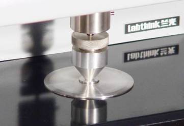
An automatic leveling structure is adopted in Labthink CHY-C1 to make presser foot parallel to the anvil surface. Once the calibration is finished, no interference is needed from the user. In addition, the two surfaces should keep from contamination and the presser foot should avoid being touched. Disassemble the instrument without permission will disable the precision of instrument.

Fig .2 CHY-C1presser foot and anvil
4.prospects
Owing to the compressible nature of flexible package, non-contact thickness testers are all limited in their application to some extent. Mechanical thickness tester has always been the top choice of various package materials. It is true that the same material will get different results under different pressure. One of the salient features in material thickness testing is to test it according to the material of package under specified pressure.
